Zener barriers: intrinsic safety solutions
These are typical system diagrams using isolation interfaces for E2S intrinsically safe sounders and beacons.
The following circuits are for illustration only, installation and details may be omitted for clarity.
Please refer to the relevant certification prior to use. As all E2S sounder and beacons have the same entity parameters in most circuits different E2S intrinsically safe field apparatus may be used providing it has the relevant input feature. Where examples show the IS-mini range a direct replacement can be made using the
IS-A105N and
IS-L101L or
combination device.
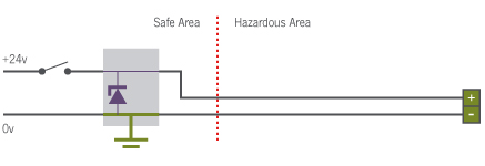
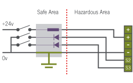
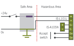
The basic installation is straightforward on/off control using a zener barrier with entity parameters 28v 93mA (often referred to as 28v 300Ω) which is an industry standard barrier (Power driver).
This is suitable for all E2S Intrinsically safe sounders and beacons.
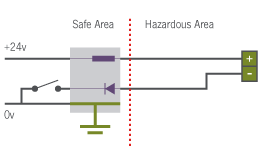
To simplify drawings the rest of the illustration do not show the representative voltage �clamping diode.
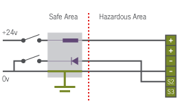
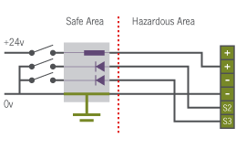
The 2nd tone on a sounder is switched down to zero volts. This can be achieved in the safe area by using a Diode return barrier.
Similarly another diode return can be added for the 3rd stage audible alarm This can be achieved with a single 3 channel barrier.
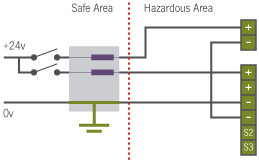
The sounder and beacon IS-mC1 or the combination of IS-105N and IS-L101 can be powered from a single zener barrier. Similarly an IS-mA1 plus IS-mb1 could be run from
a single zener barrier.
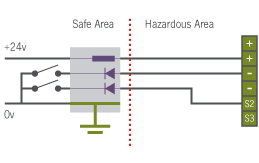
For independent control use a double channel Zener barrier.
Again with the option of 2nd tone switch. This can be extended further using 2 power and diode returns zener barriers to switch the 3rd alarm tone (not shown).
The combined IS-A105N / IS-L101L has a mute option, adding a switch will mute the alarm.
Depending on the DIP switch settings on the IS-L101 reset occurs:
On alarm condition being removed i.e. power down of IS-L101L or after a dip switch selectable interval – from 5 seconds to 2 hours.
Note the reset switch does not need to be certified as it is considered to be simple apparatus.
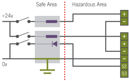
However many DCS cards use pull down signals such as open collector, common emitter outputs. Then a common power feed would be used with all switching being done via a diode return barrier.
Here is a simple on off control.
Adding another diode return gives a second stage alarm.
Should you manufacture a suitable Intrinsically safe interface or wish to comment on these applications please
contact us.
| EN1127-1 |
|
Explosive atmospheres: Explosion prevention and protection |
| Part 1: |
|
Basic concepts and methodology |
| EN 60079 |
|
ELECTRICAL APPARATUS FOR EXPLOSIVE GAS ATMOSPHERES |
| Part 0 |
|
General requirements |
| Part 14 |
|
Installation (and selection) of equipment in hazardous areas |
| Part 25 |
|
Intrinsically safe systems |
Suggested reference book on intrinsic safety and hazardous areas Electrical
Apparatus and Hazardous Areas by Robin Garside. 5th Edition 2007 ISBN
978-0-9516848-4-9


.png)